Continuiamo con la nostra serie di articoli che, attraverso esempi pratici e semplificati, dimostrano l’applicazione di strumenti fondamentali nei rispettivi ambiti. Introduciamo la configurazione base di un Switch Cisco 2960 come DHCP v4 Server su Multiple VLAN:
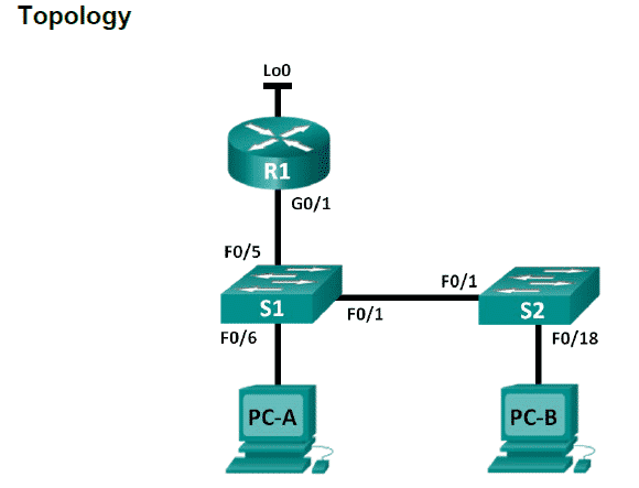
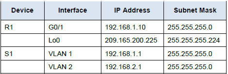
Di seguito lo schema degli indirizzi che caratterizzano la topologia oggetto del laboratorio:
Prima di procedere alla configurazione DHCP, verifichiamo quale Template SDM è precaricato sullo Switch Cisco 2960 S1. Il Template di default fornito dal Switch Database Manager (SDM) denominato “default” template non ha le funzionalità che ci occorrono per completare questo LAB. Il template adatto alle nostre esigenze è il “lanbase-routing”:
S1# show sdm prefer
The current template is "default" template.
The selected template optimizes the resources in
the switch to support this level of features for
0 routed interfaces and 255 VLANs.
number of unicast mac addresses: 8K
number of IPv4 IGMP groups: 0.25K
number of IPv4/MAC qos aces: 0.125k
number of IPv4/MAC security aces: 0.375k
Cambiamo il template dello switch S1 portandolo al lanbase-routing:
S1(config)# sdm prefer lanbase-routing
Changes to the running SDM preferences have been stored, but cannot take effect
until the next reload
The switch must be reloaded for the template to be enabled.
S1# reload
System configuration has been modified. Save? [yes/no]: no
Proceed with reload? [confirm]

S1# show sdm prefer
The current template is "lanbase-routing" template.
The selected template optimizes the resources in
the switch to support this level of features for
0 routed interfaces and 255 VLANs.
number of unicast mac addresses: 4K
number of IPv4 IGMP groups + multicast routes: 0.25K
number of IPv4 unicast routes: 0.75K
number of directly-connected IPv4 hosts: 0.75K
number of indirect IPv4 routes: 16
number of IPv6 multicast groups: 0.375k
number of directly-connected IPv6 addresses: 0.75K
number of indirect IPv6 unicast routes: 16
number of IPv4 policy based routing aces: 0
number of IPv4/MAC qos aces: 0.125k
number of IPv4/MAC security aces: 0.375k
number of IPv6 policy based routing aces: 0
number of IPv6 qos aces: 0.375k
number of IPv6 security aces: 127
Procediamo sullo Switch S1 a configurare il pool DHCP1 per la VLAN1 192.168.1.0/24 escludendo i primi 10 indirizzi e con un lease di 3 giorni:
S1(config)# ip dhcp excluded-address 192.168.1.1 192.168.1.10
S1(config)# ip dhcp pool DHCP1
S1(dhcp-config)# network 192.168.1.0 255.255.255.0
S1(dhcp-config)# default-router 192.168.1.1
S1(dhcp-config)# dns-server 192.168.1.9
S1(dhcp-config)# lease 3
Verifichiamo positivamente che il PC-A abbia ottenuti i dati di rete in DHCP:
PC-A>ipconfig
For PC-A, list the following:
IP Address: _________________________________________ 192.168.1.11
Subnet Mask: ________________________________________ 255.255.255.0
Default Gateway: _____________________________________ 192.168.1.1
For PC-B, list the following:
IP Address: _________________________________________ 192.168.1.12
Subnet Mask: ________________________________________ 255.255.255.0
Default Gateway: _____________________________________ 192.168.1.1
Adesso procediamo ad attestare il PC-A sulla VLAN2. Cambiamo la VLAN sullo switch che fa capo al PC-A e poi creiamo un Pool dedicato alla VLAN2. Quindi verifichiamo che il PC-A abbia ottenuto i dati di rete propri del nuovo Pool:
S1(config)# interface f0/6
S1(config-if)# switchport access vlan 2

PC-A>ipconfig /release
PC-A>ipconfig /renew
For PC-A, list the following:
IP Address: _________________________________________ 192.168.2.11
Subnet Mask: ________________________________________ 255.255.255.0
Default Gateway: _____________________________________ 192.168.2.1
Il PC-B appartiene ancora alla VLAN1. Ora si pone la problematica di far comunicare le 2 VLAN (quindi PC-A e PC-B) attraverso lo Switch S1. Abilitiamo il routing sullo switch S1:
S1(config)# ip routing
S1# show ip route
Codes: L - local, C - connected, S - static, R - RIP, M - mobile, B - BGP
D - EIGRP, EX - EIGRP external, O - OSPF, IA - OSPF inter area
N1 - OSPF NSSA external type 1, N2 - OSPF NSSA external type 2
E1 - OSPF external type 1, E2 - OSPF external type 2
i - IS-IS, su - IS-IS summary, L1 - IS-IS level-1, L2 - IS-IS level-2
ia - IS-IS inter area, * - candidate default, U - per-user static route
o - ODR, P - periodic downloaded static route, H - NHRP, l - LISP
+ - replicated route, % - next hop override
Gateway of last resort is not set
192.168.1.0/24 is variably subnetted, 2 subnets, 2 masks
C 192.168.1.0/24 is directly connected, Vlan1
L 192.168.1.1/32 is directly connected, Vlan1
192.168.2.0/24 is variably subnetted, 2 subnets, 2 masks
C 192.168.2.0/24 is directly connected, Vlan2
L 192.168.2.1/32 is directly connected, Vlan2
Come appuriamo dallo show della tabella di routing dello Switch S1, ci sono tutte le condizioni perchè la VLAN1 comunichi con la VLAN2 e viceversa. Il risultato è che ora il PC-A comunica con PC-B.